Click here for lightsabers
  • Home
  • Help
  • Login
  • Register
Pages: [1]   Go Down
Author Topic: How To: A Quick Recharge Port DIY  (Read 2625 times)
Niassa
Knight Ensign
*

Force Alignment: 31
Posts: 169

Niassa - Lady of the Force's Will


« on: March 29, 2012, 08:22:50 PM »

Please note: If you are not proficient with soldering, working with electricity, and Li-Ion batteries*, do not attempt this mod. I, Ultrasabers, this community, and the Force are not responsible if you destroy your saber, hurt yourself or others, burn down your house, or, well, anything else horrible! The only thing I'll be responsible for is if you successfully mod your saber in the manner described herein based on these instructions. Smiley  Performing this modification WILL void any warranty your saber has with US.

There are numerous soldering tutorials on YouTube and the Interwebs. You should also be sure to heat shrink all your connections, because again, a shorting out Li-Ion pack is a very dangerous thing. Electrical tape is NOT sufficient, it WILL fall apart after a certain amount of time.

Good luck, and may the Force be with you.

(*Lithium Ion batteries, moreso than other types of rechargeable batteries, are EXTREMELY DANGEROUS if mishandled. These batteries will rapidly overheat and may even EXPLODE if shorted out. Always remove the batteries from the battery pack while performing work!)


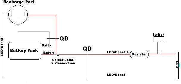
I believe I labeled everything important, and even unimportant, if I'm correct. QD stands for Quick Disconnect, which you'll probably need just to get your saber back together once this mod is done. Smiley

« Last Edit: March 29, 2012, 08:29:53 PM by ncc74656m » Logged

"I am the Force's ally - My only desire is the Force's Will." - Niassa, Corellian Jedi with Dark leanings, but always serves the light.

Sabers:
SRD Prophecy v3
GB Liberator v2 - 616 Sound
BR Dominix v2

Master Bluespike74
Guardian Prime
Vanguard of the Azure Order
Knight Commander
******

Force Alignment: 977
Posts: 4666


As long as there is light, I will be here.


« Reply #1 on: March 30, 2012, 01:45:22 AM »

Thank you very much for this information.  I have just begun today a sink tube project and I was wanting to include a recharge port and this will help tremendously. 
Logged


Guided by the Aing Tii Monks

Shodan in Shaolin Kempo Karate/Kung Fu/Jiu Jitsu

Yes, I am a color:  BLUE

Niassa
Knight Ensign
*

Force Alignment: 31
Posts: 169

Niassa - Lady of the Force's Will


« Reply #2 on: March 30, 2012, 03:27:14 AM »

Thank you very much for this information.  I have just begun today a sink tube project and I was wanting to include a recharge port and this will help tremendously. 

Most welcome!
Logged

"I am the Force's ally - My only desire is the Force's Will." - Niassa, Corellian Jedi with Dark leanings, but always serves the light.

Sabers:
SRD Prophecy v3
GB Liberator v2 - 616 Sound
BR Dominix v2

Darth Karhu
Knight Aspirant
*

Force Alignment: -1
Posts: 16


If a show of teeth isn't enough, be ready to bite.


« Reply #3 on: April 01, 2012, 06:36:43 PM »

So here's a question, how would this change if I wanted to use a 4 wire 1000mAh buck-puck with the recharge port instead of a resistor, and how would I wire an illuminated switch into the works here? (Thanks in advance for any help you're able to offer)
Logged

Dark Side points are preferred

The Collection-
CG Bellicose w 32" blade
BR Overlord w 32" blade w Obsidian (Blackstar font)
GB Dark Initiate V2 w 24" blade
BR Aeon V2 w 32" blade
AS Initiate V2 w 32" blade
AS/AS Phantasm V2 w 32" blades (en route)

Ninja-Jedi
Knight Commander
*

Force Alignment: 168
Posts: 778


« Reply #4 on: April 01, 2012, 07:07:31 PM »

The wiring diagram would be almost exacty the same except you lose the resistor, and the buck puck would wire directly to you led+ after the switch  and and the other led- basically if you are looking at the diagram the buck would wire where the led is at on the diagram, the you would just wire the led directly to the buck puck
Logged


Ninja-Jedi
Knight Commander
*

Force Alignment: 168
Posts: 778


« Reply #5 on: April 01, 2012, 07:10:36 PM »

to run illuminated switch u just run an extra set of lines of your led- and led+ and you need to resistor the led on the switch itself I would wire this in before the buck puck, their are diagrams out their already just treat the led on the switch as you would an accent led
Logged


Pages: [1]   Go Up
Send this topic | Print
Jump to: