DarthDaddy
Knight Apprentice

Force Alignment: 11
Posts: 24
|
 |
« Reply #30 on: July 01, 2014, 03:42:42 PM » |
|
Hi Everyone: I have an update on the test wire and confirming all components. Attached below is an updated wiring schematic. I discovered at least one problem source. Basically I had an open circuit from the positive battery lead through all components to the negative battery lead. This would be correct if I didn't have a recharge port, so the error was in having a wire running directly from the Ground on the Obsidian Board to the Battery -- you can see that wire in my earlier schematic posts. Below is the corrected version. In this new wiring architecture, the Obsidian Ground (plus all elements already connected to that terminal) now flow to the recharge port ground terminal. This solved the problem of the recharge port not killing all power to the obsidian when the kill key was inserted. I also moved the Power Level Indicator negative to the recharge port ground terminal. You can still wire it to the Obsidian LED terminal, but you will get a different behavior. When wired directly to recharge port ground - the PLI will illuminate when you pull the kill key, thus showing you how much battery you have without igniting the saber. But if you wire it to the Obsidian LED, the PLI will only illuminate when you ignite the saber. This is purely an individual preference and you can do it either way as it suits the individual. Now I still have one small problem. The LED on the momentary switch is still illuminated -- although when I changed the wiring the illumination decreased significantly! It was visibly illuminated before, but now you almost have to turn off the lights to see the dim glow even with the kill key inserted. This tells me that there is somehow an open circuit loop through the LED switch back to the battery. After looking at my schematic again this morning I think I know where that is. You can see the negative wire coming off the Emerald Driver and going directly to the batter negative. I think that emerald driver is still drawing a small current on the positive lead, and since the emerald driver is also connected to the Switch LED -- that might be 'pushing' a small current through. This is just an untested theory at this moment. So tonight I will test my hypothesis and move the emerald driver negative wire to the recharge port Ground. With the key in the recharge port, it will hopefully kill all power to all components and the switch LED will be completely off. So all in all -- a little good progress made in correcting the architecture - and a little more still to figure out. Thanks for all your comments and help in figuring this out.  |
|
|
|
|
 Logged
|
|
|
|
|
DarthDaddy
Knight Apprentice
Force Alignment: 11
Posts: 24
|
|
« Reply #31 on: July 02, 2014, 07:42:14 PM » |
|
OK -- final update to schematic. Everything working correctly with no errors now I think. I was correct yesterday that I need to have the emerald driver negative wire feed to the Ground of the Recharge Port. That eliminated the 'leaking' current through the switch LED. It is now 100% off when the kill key is inserted to the recharge port. Of course when the kill key is pulled everything not controlled by the obsidian soundboard fully illuminates (AV switch and Power Level Indicator). Here's the final 100% confirmed drawing:  So with test wiring now confirmed, I just need to wait on my hilt to arrive from the sabersmith. In the meantime I am going to work on a custom made lightsaber stand. I saw a website that offered these really cool LED illuminated lightsaber holders / stands with plexiglass and frosted designs in the glass. I think I can recreate the basic design with some PVC piping materials from Home Depot. I give full credit for the design to JQSabers -- visit their site -- they have some really neat things - but here's the basic idea for the design that I'm going to base my stand on.  I got some spray on rustoleum paint that resembles a textured / hammered antique pewter for the base, and I'm using lexan acrylic plexi-glass for the upper section. will post photos and design elements when I complete them.  |
|
|
|
|
Logged
|
|
|
|
|
Racona Nova
Knight of the Obsidian Order
Moderator
Knight Commander

Force Alignment: 1116
Posts: 4771
There is no good or evil....there's only power!
|
|
« Reply #32 on: July 02, 2014, 07:59:11 PM » |
|
Great to see a wiring diagram covering (almost) all possibilites and components - Recharge Port, 4-channel Emerald, Obsidian, AV switch, even that 3rd-party PLI! Also the saber stands - just awesome...
However, I have some questions:
1) Could you also come up with wiring diagrams covering the "in line with channel" and "dedicated to channel" options for the illuminated AV switch? From what I read in your description, this wiring diagram shows the "Always On" option (if no Kill Key is inserted), right?
2) Did you also use a 20mA Dyna-Ohm for the AV switch?
3) Are those Accent RGB LEDs also available with a fourth die, just like the main LED? Would be cool if White/Amber is possible for that Accent RGB LED, too.
|
|
|
|
« Last Edit: July 02, 2014, 08:06:24 PM by Racona Nova »
|
Logged
|
Sig by Master Nero Phantasm v3 LE (Obs v3) - AB w/ FoC AS---Manticore (Obs v3) - BR w/ FoC AS (QD)---Archon v2.1 (Obs v3) - RGBW Emerald |
|
|
|
James Casey
Forum Watchman
Knight Commander

Force Alignment: 1510
Posts: 5981
|
|
« Reply #33 on: July 02, 2014, 08:10:04 PM » |
|
1) Could you also come up with wiring diagrams covering the "in line with channel" and "dedicated to channel" options for the illuminated AV switch? From what I read in your description, this wiring diagram shows the "Always On" option (if no Kill Key is inserted), right?
I'd also be interested in this, as I'm considering modifying the always-on switch on my Bane to being in series to one of the channels but right now I have no idea how to go about that  |
|
|
|
|
Logged
|
 "I'll split this world open and tear down the sky before I let him come to even the slightest harm." |
|
|
|
DarthDaddy
Knight Apprentice
Force Alignment: 11
Posts: 24
|
|
« Reply #34 on: July 03, 2014, 07:16:50 PM » |
|
However, I have some questions:
1) Could you also come up with wiring diagrams covering the "in line with channel" and "dedicated to channel" options for the illuminated AV switch? From what I read in your description, this wiring diagram shows the "Always On" option (if no Kill Key is inserted), right?
2) Did you also use a 20mA Dyna-Ohm for the AV switch?
3) Are those Accent RGB LEDs also available with a fourth die, just like the main LED? Would be cool if White/Amber is possible for that Accent RGB LED, too.
1) I will think on the architecture for that wiring and try to come up with the diagram in my spare time. It might be a while before I can create and post that. I think it would just be a matter of wiring the positive lead on the switch led between the emerald driver and one of the positive color led die leads. You have to remember though that your switch will only illuminate when you are using the color in question. So if you wire it to your red positive lead but you go with 100% blue your switch will not illuminate because the emerald driver is preventing power from going through the red led die. If you want the switch led to illuminate you will have to increase the color intensity of the chosen in line color. Even then it may not illuminate fully because you may be using such a low setting on that color that the current flowing is not enough to reach the full 20ma. Food for thought before you build. 2) no. I used a standard static resistor calculated from a 7.4 volt power source and 20ma forward current. I think the resistor was something like a 1/4 watt 220 or 250 ohm. 3) I haven't personally seen a four due accent led. But doesn't mean it doesn't exist. I did see a 3 watt version that has a pretty small profile but I don't think I will use that considering the power drain on the battery. Adding a four die accent led will also probably drain the battery pretty quickly. Even with simple rgb you will end up with nearly limitless possibilities and colors close enough to pass for match with main led. |
|
|
|
|
Logged
|
|
|
|
|
Racona Nova
Knight of the Obsidian Order
Moderator
Knight Commander
Force Alignment: 1116
Posts: 4771
There is no good or evil....there's only power!
|
|
« Reply #35 on: July 03, 2014, 07:22:10 PM » |
|
Thanks for that really helpful answer, I will keep everything in mind if I start a similar project...right now I don't have the space, time and money for this.
Point for you!
|
|
|
|
|
Logged
|
Sig by Master Nero Phantasm v3 LE (Obs v3) - AB w/ FoC AS---Manticore (Obs v3) - BR w/ FoC AS (QD)---Archon v2.1 (Obs v3) - RGBW Emerald |
|
|
|
Jedijosh
Knight Commander
Force Alignment: 105
Posts: 1332
Come back to the light side we have chips & Salsa
|
|
« Reply #36 on: July 03, 2014, 07:54:44 PM » |
|
This has been really helpful in helping me remember what my dad has taught me about maintaining and repairing vacuum cleaners:). Thank you. recently put it into practice and was able to do a minor maintenance which had been sounding like a major repair:). Also I am hoping to use this to build my own stuntsaber:).
|
|
|
|
|
Logged
|
Sabers:
Aeon v2 (CG), Archon v2.1 (VA), Graflex CE (Obsidian Emerald), Guardian (Obsidian GB),
Wish list:
Azure Mantis, Arbiter, Bellicose in RGB, Chosen One CE, Consular in CG, Prophecy v3
|
|
|
|
Brian64
Knight Commander
Force Alignment: 149
Posts: 700
This is a fertile land, and we will thrive
|
|
« Reply #37 on: July 19, 2014, 12:15:17 AM » |
|
Thanks very much for the info DarthDaddy.
It's times like this I wish I took electronics at school...
A few of my early Emeralds have the AV switch dedicated to channel 4, that I now really wish now were in series with channel 4. But I can't read a wiring diagram, and shipping half a dozen sabers back to Emory from Australia isn't going to be a cheap option. I'd sooner spend the money on some new sabers.
I'm adding a light side point since your points are currently in the +, but if you prefer a sith point just let me know.
|
|
|
|
|
Logged
|
 Light side points please |
|
|
|
Racona Nova
Knight of the Obsidian Order
Moderator
Knight Commander
Force Alignment: 1116
Posts: 4771
There is no good or evil....there's only power!
|
|
« Reply #38 on: July 19, 2014, 08:05:54 PM » |
|
I think I know how to wire it to have it in series. Just connect the LED + of the switch to the wire leading to the + of your desired channel, e.g. Ch1 or Ch4 instead of connecting it to the wire leading from the battery pack to the Emerald Driver and the VIN on the Obsidian soundboard. For the dedicated option, it's similar: Just wire the LED + of the switch directly to the + of your desired channel on the Emerald Driver, leaving the corresponding + on the main LED blank. These are guesses, however, so it would be great if anyone could confirm my thoughts  |
|
|
|
|
Logged
|
Sig by Master Nero Phantasm v3 LE (Obs v3) - AB w/ FoC AS---Manticore (Obs v3) - BR w/ FoC AS (QD)---Archon v2.1 (Obs v3) - RGBW Emerald |
|
|
|
Mikeyeggy
Knight Aspirant
Force Alignment: 6
Posts: 14
|
|
« Reply #39 on: August 05, 2014, 10:30:45 PM » |
|
Maybe I'm wrong, but it seems to me that you can reduce the overall number of wires that go to the Main/Accent LED. After reviewing your wiring diagram, it seems to me that all your (-) leads are basically shorted together now. So, why not just short them all together up on the LED and on the board and then run just one "ground" wire for the LED? To me it seems logical and space relieving.
|
|
|
|
|
Logged
|
|
|
|
|
Racona Nova
Knight of the Obsidian Order
Moderator
Knight Commander
Force Alignment: 1116
Posts: 4771
There is no good or evil....there's only power!
|
|
« Reply #40 on: August 06, 2014, 04:19:00 PM » |
|
You may use a multicore wire (with 4 cores) that are split at the LED's solder pads and the board, but then you have to use a multicore wire (with three cores) for the accent LED's connection to the multicore wire leading to the board. Then you need to know which of the four cores controls which die and then connect your accent LED's wire cores to the appropiate cores of the main LED's wire.
It would be more space-saving, yes, but the effort to do this is much higher than with the single wires solution. And the whole build would become more rigid with those multicore wires, which means you can't pull out the battery pack that easily.
|
|
|
|
|
Logged
|
Sig by Master Nero Phantasm v3 LE (Obs v3) - AB w/ FoC AS---Manticore (Obs v3) - BR w/ FoC AS (QD)---Archon v2.1 (Obs v3) - RGBW Emerald |
|
|
|
DarthDaddy
Knight Apprentice
Force Alignment: 11
Posts: 24
|
|
« Reply #41 on: August 13, 2014, 01:03:44 AM » |
|
Maybe I'm wrong, but it seems to me that you can reduce the overall number of wires that go to the Main/Accent LED. After reviewing your wiring diagram, it seems to me that all your (-) leads are basically shorted together now. So, why not just short them all together up on the LED and on the board and then run just one "ground" wire for the LED? To me it seems logical and space relieving.
I don't think you can short the negatives together. When ultra sabers sent me the pre-wired led module they had a total of 8 wires (4 positives and 4 negatives). Each of these wires must be attached to a corresponding terminal on the emerald board. I'm no expert in electronics but I think the reason for this is that the emerald driver controls the current running through each of the four dies independently of one another and so if you short all the negatives together into a common ground you'll be combining current flow for the four dies together which at best may not allow the led to function and at worst blow out the emerald driver. Like I said; I'm far from an expert in this field but it seems logical to me and I'm not one for trying this on a $125 board. |
|
|
|
|
Logged
|
|
|
|
|
DarthDaddy
Knight Apprentice
Force Alignment: 11
Posts: 24
|
|
« Reply #42 on: August 13, 2014, 02:11:05 AM » |
|
Hi all It's been a long time since I've posted progress. I'm still waiting on some custom machined parts for the hilt but it should be coming in this week or next. In the interim I wanted to show progress on the display stand I've been making. You can see from the earlier posts that I was trying to recreate the basic design from a led lit display from jqsabers.com Here's some photos of what I accomplished. First photo is the way it looks unlit. The base is a large PVC pipe coupling that has been dremmeled to create the sloping flanged look. And it has been painted with a rust oleum 'hammered' pewter. The paint comes out in that textured way. So no special skills  The upper part is lexan acrylic and the painted design on the left reads 'Jedi Master' and on the right 'Sith Lord' in Aurbesh. I drew the pattern lines on the sheet of acrylic and then carefully dremmeled them out. Sanded the edges to make them smooth and flush. The base is made of two acrylic disks. One is sanded to be translucent and the other is clear with the Jedi order symbol painted. There are holes cut into the base that allow the vertical pieces to seat firmly.  This next photo shows the underside of the stand and the led strip inside. This led strip was a stroke of good luck. You can find this at Fry's or another electronics store. You don't need any knowledge of power source or resistor calculation. Just plug into a 12 volt outlet cord. Also purchased at Fry's. The total cost of this led strip was about $25 all in. The led strip is sticky on the backside but I still put some clear silicone caulk on it to permanently hold in place. 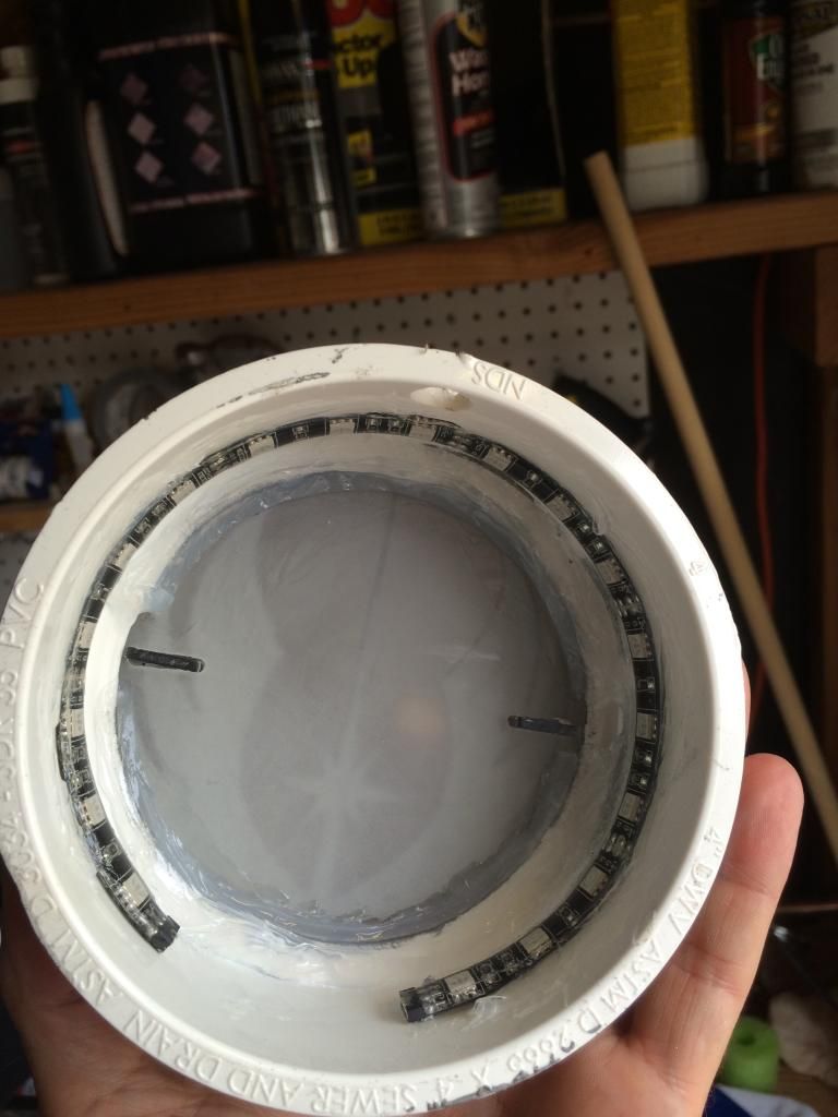 Here's the little remote control for the led. It can change to 16 different colors and it can strobe or fade through the colors. Personally watching it strobe through the colors hurts my eyes so I will leave it a single color. 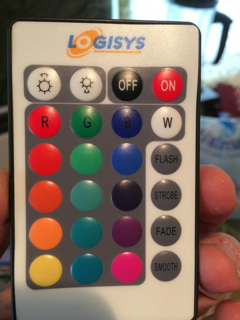 And lastly, here are just a few examples of the color effects. This is going to go well with the emerald saber because I can roughly change the stand illumination to match blade and crystal color configured on the saber. 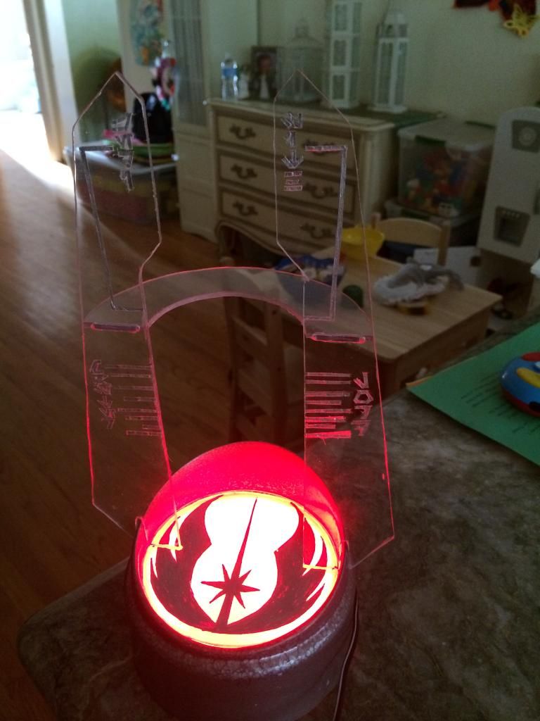 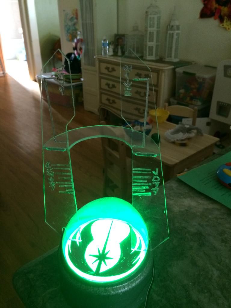 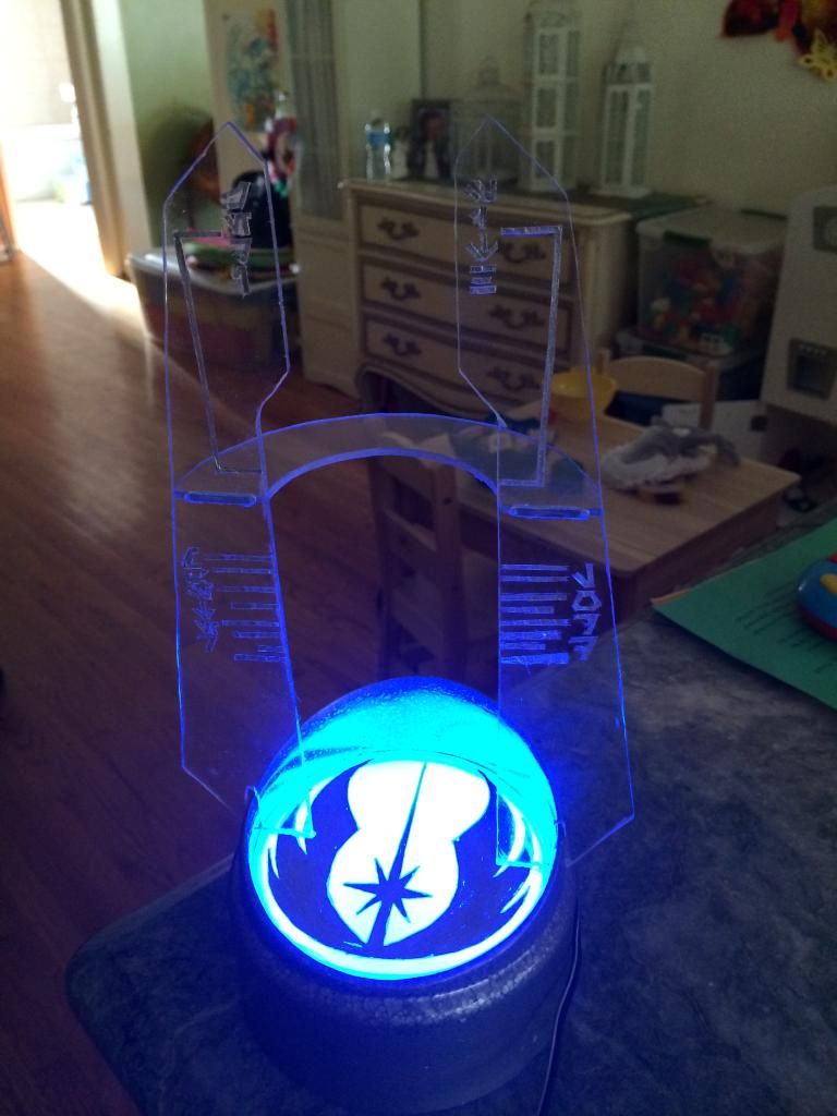 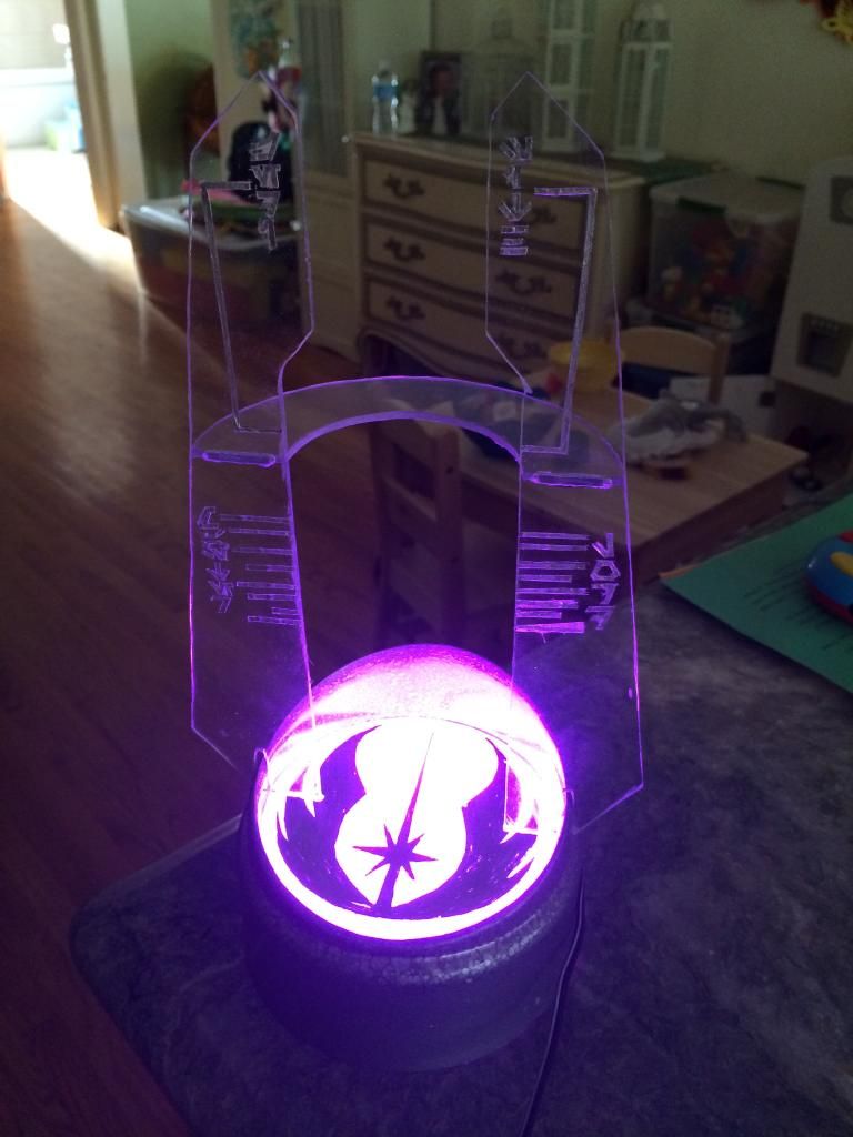 |
|
|
|
|
Logged
|
|
|
|
|
sedstiskyfaller
Artisan of the Azure Order
Knight Commander
Force Alignment: 617
Posts: 2214
Blue is my color, it is who I am

|
|
« Reply #43 on: August 13, 2014, 04:12:19 AM » |
|
Great job on the stand! It looks awesome.
|
|
|
|
|
Logged
|
|
|
|
|
Mikeyeggy
Knight Aspirant
Force Alignment: 6
Posts: 14
|
|
« Reply #44 on: August 13, 2014, 10:15:38 PM » |
|
I'd like to confirm that you can short all the negatives together. I rewired my Emerald Shock LE and I did just that. On the driver, the negatives are already shorted together as a common ground. All I had to do was short all the negs on the LED to basically turn it into a common Cathode LED. After that I ran one single ground back, and it is working beautifully.
|
|
|
|
|
Logged
|
|
|
|
|
|