Ultra
Lord Commander
Administrator
Knight Commander

Force Alignment: 1765
Posts: 2194
IN HOC SIGNO VINCES

|
 |
« on: June 12, 2011, 07:45:50 AM » |
|
 Obsidian uses a wiring harness, so no board level soldering is required. Just make sure the right wires are going to the right places based on this diagram. Reverse polarity on the input can damage the board, so please be double sure you're connecting things properly. If you don't understand this diagram, do not attempt a sound board install. Novastar made this one to help you out even more: .jpg) |
|
|
|
« Last Edit: February 26, 2013, 07:15:57 AM by Deep »
|
 Logged
|
|
|
|
|
The_Night
Knight Lt. Commander

Force Alignment: -38
Posts: 470
"If it's not fun, you're not doing it right"
|
|
« Reply #1 on: June 12, 2011, 09:28:40 AM » |
|
ok, the coloring/ placement on the diagram are slightly confusing. when wiring, do you wire the LED to the battery and the VIN lead on the board? or just to the board itself? same thing for the push button- does it go to the battery and the board or just the board? hope my question makes sense... thanks  |
|
|
|
|
Logged
|
Vintage Graflex ANH
Vintage Graflex ESB
Custom Hero LS6- PCU
JQ Quinlan Vos- PCU
MR Maul Staff- P4 Reds
MR Vader ESB FX
UFX Vader ANH- Lux3 Red
Larbel Obi TPM- CF v5.1
Parks Obi ANH
|
|
|
|
Kant Lavar
Knight Aspirant

Force Alignment: 0
Posts: 12
Force-sensitive MechWarrior
|
|
« Reply #2 on: June 12, 2011, 09:13:17 PM » |
|
It looks like one switch lead goes with the negative pole of the battery to the GND (ground) terminal on the board, and the positive leads of both the battery and LED go to the VIN (voltage in) terminal. I'll fire up TinyCAD and see if I can't make a diagram that's a bit clearer. EDIT: Here we go. This should (hopefully) make things a little easier to understand. I left out the C1 terminals that Ultra showed, given that they weren't hooked up to anything. I suspect those are for the USB port that will be already soldered in, or perhaps for a sensor. Either way, I don't think it matters to the end-user. (If I'm wrong, well, Force knows it wouldn't be the first time!) 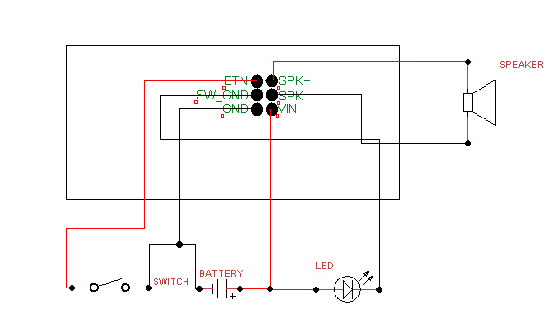 |
|
|
|
« Last Edit: June 12, 2011, 09:27:09 PM by Kant Lavar »
|
Logged
|
When in doubt, C-4. - Jamie Hyneman Proud member of the REBEL LEGION
|
|
|
|
Novastar
Disgraced
Knight Arbiter

Force Alignment: 110
Posts: 284
|
|
« Reply #3 on: June 13, 2011, 10:04:53 AM » |
|
Oh SNAP, Kant. You're the man... you're the MAN for helping out like that! Much thanks!!
EDIT:
If I recall (and I may be wrong)... the wiring harness itself MAY have each wire separately colored... so it may become a non-issue if we eventually say "black = gnd... red = vin", etc.
Additionally, it will be advantageous to mark them as pins 1-6 at a certain point, and explain which pins share what, such as ("vertically from the left"):
PIN 1 = momentary switch / button
PIN 2 = LED - (Negative)
PIN 3 = Batt - (Negative / Ground) and also secondary switch lead
PIN 4 = SPK + (Positive) ---|
PIN 5 = SPK - (Negative) ------ in general, the SPK leads are interchangeable on a mono speaker setup
PIN 6 = Batt + (Positive) and also LED + (Positive)
If I made some error with this "pin" setup, please edit / correct / etc.
|
|
|
|
« Last Edit: June 13, 2011, 10:16:44 AM by Master Novastar »
|
Logged
|
Creator of the "BALANCE OF POWER" live staged-combat shows
Licensed & experienced sabre fencing instructor
Sound font engineer for "Crystal Focus" & Obsidian
Creator of the NSCFCDs (CF Sound CDs)
Co-Founder of Golden Gate Knights (SF)
Co-Creator of NCSCS (Nova & Caine's Saber Combat System)
|
|
|
|
Ultra
Lord Commander
Administrator
Knight Commander
Force Alignment: 1765
Posts: 2194
IN HOC SIGNO VINCES
|
|
« Reply #4 on: June 13, 2011, 01:37:44 PM » |
|
Nova, that is why you can't leave C1 off the diagram. C1 is the capacitor for the class D amplifier. It's next to the wiring harness and by using it as a point of reference, you will know what wires go where.
|
|
|
|
|
Logged
|
|
|
|
|
Kant Lavar
Knight Aspirant
Force Alignment: 0
Posts: 12
Force-sensitive MechWarrior
|
|
« Reply #5 on: June 13, 2011, 08:58:48 PM » |
|
Oh SNAP, Kant. You're the man... you're the MAN for helping out like that! Much thanks!!
TinyCAD is awesome. It took me all of maybe an hour to put together a diagram for my proton pack electronics, for example. And that included looking up some stuff. And, of course, the price can't be beat. Nova, that is why you can't leave C1 off the diagram. C1 is the capacitor for the class D amplifier. It's next to the wiring harness and by using it as a point of reference, you will know what wires go where.
Huh. Are the pins more centered than I thought? Granted, I haven't had a good look at an Obsidian board (yet!) they looked far enough off-center that it should be easy enough to orientate the board to a schematic regardless... Also, something I thought of while I was looking at this: I didn't see anything referenced for an AV switch LED; is that only an option that you guys will be able to do in-house, or will someone doing an install in their own saber be able to wire that up? I know the end-user could just parallel the AV LED off the blade LED output, but I do like the off-mode blinky. |
|
|
|
|
Logged
|
When in doubt, C-4. - Jamie Hyneman Proud member of the REBEL LEGION
|
|
|
|
ultimatebob
Knight Apprentice
Force Alignment: 4
Posts: 32
my ULTIMATENESS blinds you.
|
|
« Reply #6 on: June 14, 2011, 10:31:00 AM » |
|
what is C1?
|
|
|
|
|
Logged
|
Dominix V2 LE -consular green
Aeon -blazing red
|
|
|
|
ultimatebob
Knight Apprentice
Force Alignment: 4
Posts: 32
my ULTIMATENESS blinds you.
|
|
« Reply #7 on: June 14, 2011, 10:37:40 AM » |
|
wait a sec ultra just answered that. (facepalm)
|
|
|
|
|
Logged
|
Dominix V2 LE -consular green
Aeon -blazing red
|
|
|
|
Machinimax
Force Sensitive

Force Alignment: 0
Posts: 9
|
|
« Reply #8 on: June 15, 2011, 02:47:01 PM » |
|
I'd hate to be "that guy" but can someone make a wiring diagram that shows how to install a recharge port into the circuit? If anyone does, MUCH THANKS!!!
|
|
|
|
|
Logged
|
|
|
|
|
Evesbane
Knight Apprentice
Force Alignment: -1
Posts: 22
|
|
« Reply #9 on: June 15, 2011, 03:02:36 PM » |
|
Positive from Board (VIN) and batt pack goes to central pin, and the neg from board(GND) and neg from pack are on opposite switches pins. I'll try and get a pic fast. Correct me if I'm wrong, but I'm pretty sure that's how it works. http://www.plecterlabs.com/Media/Doc/RechargePort.jpgHope the labs site is ok to link =\ |
|
|
|
« Last Edit: June 15, 2011, 03:09:14 PM by Evesbane »
|
Logged
|
|
|
|
|
Machinimax
Force Sensitive
Force Alignment: 0
Posts: 9
|
|
« Reply #10 on: June 15, 2011, 03:37:43 PM » |
|
Positive from Board (VIN) and batt pack goes to central pin, and the neg from board(GND) and neg from pack are on opposite switches pins. I'll try and get a pic fast. Correct me if I'm wrong, but I'm pretty sure that's how it works. http://www.plecterlabs.com/Media/Doc/RechargePort.jpgHope the labs site is ok to link =\ Wonderful!!! Thanks a million!!! |
|
|
|
|
Logged
|
|
|
|
|
The_Night
Knight Lt. Commander
Force Alignment: -38
Posts: 470
"If it's not fun, you're not doing it right"
|
|
« Reply #11 on: June 15, 2011, 10:30:39 PM » |
|
how did you get the AV switch wired up as an indicator LED without additional LED pads on the board?
|
|
|
|
|
Logged
|
Vintage Graflex ANH
Vintage Graflex ESB
Custom Hero LS6- PCU
JQ Quinlan Vos- PCU
MR Maul Staff- P4 Reds
MR Vader ESB FX
UFX Vader ANH- Lux3 Red
Larbel Obi TPM- CF v5.1
Parks Obi ANH
|
|
|
|
Ultra
Lord Commander
Administrator
Knight Commander
Force Alignment: 1765
Posts: 2194
IN HOC SIGNO VINCES
|
|
« Reply #12 on: June 16, 2011, 04:48:04 AM » |
|
Geez, people, you don't need the board to do EVERYTHING for you. I can wire up accent LEDs without any kind of soundboard and I can make them blink/fade/flicker with any manner of inexpensive components. You should be able to also if you're even attempting a DIY install.
|
|
|
|
|
Logged
|
|
|
|
|
Caine
Disgraced
Knight Commander

Force Alignment: -129
Posts: 507
|
|
« Reply #13 on: June 16, 2011, 05:02:52 AM » |
|
Geez, people, you don't need the board to do EVERYTHING for you. I can wire up accent LEDs without any kind of soundboard and I can make them blink/fade/flicker with any manner of inexpensive components. You should be able to also if you're even attempting a DIY install.
exactly. if you all want to wire AV switches and accent LED's, you just need to run them off the main LED but running them parallel. Don't know what parallel means? At one time, neither did I. Do some internet research. Where do you get accent LED's Do some research. Where do you learn DIY saberbuilding.....DO SOME RESEARCH. No offense peeps, but no one is going to spoon feed information. ALL of us learned this way. When I was learning to build sabers, I would always ask Nova stuff and although he guided me, he never directly told me how to do something. He told me to go look it up...so I did. Tough love? Sure. But you'll live....and so did I. |
|
|
|
|
Logged
|
|
|
|
|
zenid
Force Sensitive
Force Alignment: 0
Posts: 1
|
|
« Reply #14 on: June 16, 2011, 08:17:38 AM » |
|
Just to get it straight and prevent frying LEDs or the whole board. According to the wiring diagramm you don't need any additional resistor or something? Is there any battery type I should use or is this board really that universal?
And one more thing, what are the exact dimensions of the board?
regards from europe!
|
|
|
|
|
Logged
|
|
|
|
|
|