|
|
 |
« on: June 25, 2015, 11:41:30 AM » |
|
Hey guys, I need help with wiring a project together. This is going to be practice for a completely custom built saber that I'm going to buy emerald and obsidian guts for, but I'm using a 6 pin buck puck, an illuminated momentary switch, and a white LED. However, I can't find a diagram that doesn't include a sound board.
|
|
|
|
|
 Logged
|
Owned:
Flamberge- Obsidian, AS
Prophecy V3- AS(Green disc combo)
Wanted:
Guardian- Obsidian, GB
|
|
|
|
Groovidad
Knight Commander

Force Alignment: -203
Posts: 997
Darth Groove
|
|
« Reply #1 on: June 25, 2015, 04:48:49 PM » |
|
Hey guys, I need help with wiring a project together. This is going to be practice for a completely custom built saber that I'm going to buy emerald and obsidian guts for, but I'm using a 6 pin buck puck, an illuminated momentary switch, and a white LED. However, I can't find a diagram that doesn't include a sound board.
This is the thread with wiring diagrams: http://www.saberforum.com/index.php?topic=8667.0On the Emerald board, I don't think you can buy that from US, UNLESS you have worked out a "deal" with Emory(?) It's not a product they sell under "Build Your Own Saber". If you can get one, sweet! Good luck!  |
|
|
|
|
Logged
|
Failure is NOT an option!
ARSENAL
Dark Initiate LE v3; BR w/VA FoC; OBS v4
Chosen One CE; BR w/AS FoC; AV red; OBS v4
Dominix LE v3; VA W/AB FoC, AV red, OBS v4
Dark Liberator v3; FO, OBS v3
Guardian CE; Emerald, Black AV yellow, OBS v4
Sentinel v4, Windows, SRD w/AB FoC, Silver AV blue, OBS v4
Graflex SE, Emerald, silver AV, Brass buttons, OBS v3
Prophecy, GB blade, OBS v3, Silver AV
Standard Issue BS, GB w/VA FoC, Silver AV Green, OBS v3
Crimson Reaper, Emerald, Silver AV Blue, OBS v3, recharge port
Crimson Liberator, Stunt
Archon v2.1; CG w/AS FoC, AV Blue, OBS v4
|
|
|
|
Racona Nova
Knight of the Obsidian Order
SaberForum.Com Moderator
Knight Commander

Force Alignment: 1116
Posts: 4771
There is no good or evil....there's only power!
|
|
« Reply #2 on: June 25, 2015, 08:40:17 PM » |
|
Without a sound board you can't use a momentary switch. You have to get a latching switch instead. What power source do you want to use? NiMH rechargeables or Li-Ion setup? Wiring it without a sound board is not that difficult, you can get the correct wiring from the diagrams above - with some modifications, of course  However, I can't tell you exactly how you have to modify it (haven't done a DIY project yet and very little knowledge about electronic stuff)...maybe a DIY expert can help you better  |
|
|
|
« Last Edit: June 25, 2015, 08:44:36 PM by Racona Nova »
|
Logged
|
Sig by Master Nero Phantasm v3 LE (Obs v3) - AB w/ FoC AS---Manticore (Obs v3) - BR w/ FoC AS (QD)---Archon v2.1 (Obs v3) - RGBW Emerald |
|
|
|
|
|
|
« Reply #3 on: June 28, 2015, 10:49:25 AM » |
|
Ok, this may be another stupid question. I have the illuminated latching switch and a 6 pin buck puck. can the buck puck act as a resistor for both the switch and LED?
|
|
|
|
|
Logged
|
Owned:
Flamberge- Obsidian, AS
Prophecy V3- AS(Green disc combo)
Wanted:
Guardian- Obsidian, GB
|
|
|
|
Racona Nova
Knight of the Obsidian Order
SaberForum.Com Moderator
Knight Commander
Force Alignment: 1116
Posts: 4771
There is no good or evil....there's only power!
|
|
« Reply #4 on: June 28, 2015, 04:53:06 PM » |
|
No, you always need a separate resistor for the switch LED, even with a BuckPuck. The forward voltages and currents of the switch and main LEDs are just too different.
|
|
|
|
|
Logged
|
Sig by Master Nero Phantasm v3 LE (Obs v3) - AB w/ FoC AS---Manticore (Obs v3) - BR w/ FoC AS (QD)---Archon v2.1 (Obs v3) - RGBW Emerald |
|
|
|
|
|
|
« Reply #5 on: July 08, 2015, 09:21:46 AM » |
|
Ok, new question, same topic. I Want to upgrade my stunt saber to have an illuminated switch. I have all the parts, however, I cannot find a wiring schematic that only uses a resistor and no buck puck. Can anyone help?
|
|
|
|
|
Logged
|
Owned:
Flamberge- Obsidian, AS
Prophecy V3- AS(Green disc combo)
Wanted:
Guardian- Obsidian, GB
|
|
|
|
JediXIX
Alchemist of the Sentinel Order
Knight Commander
Force Alignment: 1172
Posts: 2190
|
|
« Reply #6 on: July 08, 2015, 02:07:26 PM » |
|
Hi Kal-El_Kenobi1138, I've done quite a few now, I do things a little different from my first, but this link was my first and may help you a bit http://www.saberforum.com/index.php?topic=22628.msg348595#msg348595As you can see in one of the pics I just put the main LED resistor in the wires leading to the LED module instead of using a Buckpuck..... I found this wiring diagram helpful, but of course it shows a Buckpuck.....  Cheers |
|
|
|
|
Logged
|
Remember... The Force will be with you... Always . . . (Just let it in)
|
|
|
|
|
|
|
« Reply #7 on: July 08, 2015, 02:45:21 PM » |
|
so would i just put the switch resistor before the positive end on the switch (between it and the battery)?
|
|
|
|
|
Logged
|
Owned:
Flamberge- Obsidian, AS
Prophecy V3- AS(Green disc combo)
Wanted:
Guardian- Obsidian, GB
|
|
|
|
JediXIX
Alchemist of the Sentinel Order
Knight Commander
Force Alignment: 1172
Posts: 2190
|
|
« Reply #8 on: July 08, 2015, 02:52:57 PM » |
|
For the switch LED resistor, it goes between the V-Out (+) on the m/l board and the (+) terminal for the LED on the switch.....
|
|
|
|
|
Logged
|
Remember... The Force will be with you... Always . . . (Just let it in)
|
|
|
|
|
|
|
« Reply #9 on: July 08, 2015, 03:20:16 PM » |
|
This is just a stunt saber without sound, so I don't have a sound board and its latching, not momentary.
|
|
|
|
|
Logged
|
Owned:
Flamberge- Obsidian, AS
Prophecy V3- AS(Green disc combo)
Wanted:
Guardian- Obsidian, GB
|
|
|
|
Sarich Belmont
Knight Commander
Force Alignment: 54
Posts: 599
I am legend.
|
|
« Reply #10 on: July 08, 2015, 04:47:19 PM » |
|
The board pictured in the diagram isn't a soundboard. It's a board that allows you to use a momentary switch as though it were a latching switch.
|
|
|
|
|
Logged
|
"I don't aim to be like you, Master, not at all. I aim to be better." Jacen Sarich, then-Padawan. (From my old Star Wars D20 days.)
Under Construction...
|
|
|
|
JediXIX
Alchemist of the Sentinel Order
Knight Commander
Force Alignment: 1172
Posts: 2190
|
|
« Reply #11 on: July 09, 2015, 05:00:12 AM » |
|
This is just a stunt saber without sound, so I don't have a sound board and its latching, not momentary.
Ok.... I've been putting momentary av's into my stunt sabers using a m/l converter..... sorry bout that so would i just put the switch resistor before the positive end on the switch (between it and the battery)?
I don't have a clear diagram, only some scribbled notes, lol, but..... a latching illuminated av switch has 5 pins, C1, NO1, NC1, LED+, LED-, and the switch LED resistor would go between a wire looped from NO1 to LED+ on the switch, and the main LED resistor would go between a wire from NO1 and the + on the LED module..... hope that helps |
|
|
|
|
Logged
|
Remember... The Force will be with you... Always . . . (Just let it in)
|
|
|
|
|
|
|
« Reply #12 on: July 09, 2015, 07:36:29 AM » |
|
I think so. Thank you.
|
|
|
|
|
Logged
|
Owned:
Flamberge- Obsidian, AS
Prophecy V3- AS(Green disc combo)
Wanted:
Guardian- Obsidian, GB
|
|
|
|
|
|
|
« Reply #13 on: July 09, 2015, 10:46:12 AM » |
|
Ok, So if I'm understanding this correctly, this is how it's supposed to look right. with the yellow dots being the soldering points on the switch. 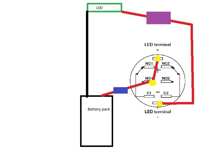 |
|
|
|
|
Logged
|
Owned:
Flamberge- Obsidian, AS
Prophecy V3- AS(Green disc combo)
Wanted:
Guardian- Obsidian, GB
|
|
|
|
Racona Nova
Knight of the Obsidian Order
SaberForum.Com Moderator
Knight Commander
Force Alignment: 1116
Posts: 4771
There is no good or evil....there's only power!
|
|
« Reply #14 on: July 09, 2015, 03:24:12 PM » |
|
I think your current connection leading from the main LED to the LED (-) of the switch has to go to the NO1 terminal of the switch instead. The resistor for the switch has to be moved between the NO1 and the LED (+) of the switch. And you also need a connection from the negative coming from the battery pack to the LED (-) of the switch. I'm no expert, but I'm quite sure that it should work after you add/change these connections.
|
|
|
|
|
Logged
|
Sig by Master Nero Phantasm v3 LE (Obs v3) - AB w/ FoC AS---Manticore (Obs v3) - BR w/ FoC AS (QD)---Archon v2.1 (Obs v3) - RGBW Emerald |
|
|
|
|